2013-08-19

Robot leg anatomy

Here is (mostly for my own reference) a simple glossary for the parts that go into a very simple robot leg, with illustration.

The leg is divided into 4 parts:
  1. Hip (Coxa)
  2. Thigh (Femur)
  3. Shin (Tibia)
  4. Foot (Tarsus)
I prefer simplicity so I will use the names in English, while others will prefer the names in Latin.

In my robot, there is no Foot, I just included that for completeness. Also this referece lacks any mention of joints or muscles (actuators). I simply lists the bones or "links".

Anatomy of robot legg showing Hip, Thigh, Shin, Foot (Coxa, Femur, Tibia, Tarsus).
I used wikipedia and this site for inspiration and reference: http://bugs.osu.edu/~bugdoc/Shetlar/462/462InsectMorphology/Morph03.htm

2013-08-18

Good bye ODE, hello GEAR!

I eventually grew tired of ODE's inability to handle cyclic graphs well, and looked for alternatives. Apparently cyclic dependencies in the constraints is a difficult problem to solve so very few solutions exist that will work. Luckily I found an alternative called GEAR (Geometric Engine for Articulated Rigid-body simulation) which was made with cyclic graphs in mind. GEAR is an implementation of a a novelty algorithm using some fancy new stuff called "lie group formulation for articulated rigid body dynamics". The code speaks for itself. Mr. Jinwook Kim who made the original, and Mr. Junggon Kim who adapted it to his use (and from what I can see, extended/simplified the code a bit) really know what they were up to. It seems to use more is nearer to use some basic C++ features and lacks the silly "C <--> C++ <--> C" wrapping of the ODE API. There seems to be no documentation what-so-ever, except for the extremely math-intensive and otherwise dense paper, and code comments are sparse. But the demos are stunning! Please check out the videos on this page.

"Sloop" demo of GEAR
I will make my best effort to use this code in my project, and if I am lucky, it will perform under my demands. One hurdle that I will have to get around is the lack of collision detection and handling, however there is some code for that on the video page that I might be able to adapt.

UPDATE: gear was moved to github.

2013-08-13

Riftcam

I have previously written about OpenGL code for the ocular rift, and Now after receiving my own I have yet to go further with writing the perspective correction code. The truth is that even if the rift is one awesome piece of gadget that I believe will change the way we interact with computers in the near future, I still have a strong mandate in this project that I have to prioritize, and that is to build my robot. Until I actually need the rift for something in my project, It will be sitting in its box.

Oculus rift illustration 
That being said, I have contacted several surveillance camera manufacturers on Alibaba with requests about creating a stereo vision PTZ dome camera with oculus compatible wide angle lenses. I actually had some response in this regard. I will keep this blog updated.


ODE instability

Adding the actuators to my ODE model proved much harder than first anticipated. Even with all the stability-enhancing features of ODE cranked up to the max (really small step size, CFM and ERP set high, unit size bodies, masses etc.) my model completely explodes. I think the reason is that when I pose the model, it is not completely still, and the abrupt movement caused by the spike in error correction at simulation startup simply blows out of proportions.

Open Dynamics Engine (ODE) exploded simulation due to instability.

I will work on it some more before giving up on it. One idea is to engage the actuator bodies after the rest of the model has settled. Maybe assembling the model in zero gravity will help as well. But so far it is not looking good for this project. :-( I was hoping that ODE would play nice. I have used it a lot before, but then I mostly played with the collision detection and building large structures out of blocks to see how they would collapse, which ODE handled splendidly.

In my frustration I went looking for alternatives and found this excellent collection of hexapod code by 12Cent Dwarf

2013-08-12

First ODE based IK screenshot

I finally managed to coax ODE into accepting my IK rig. It was not easy, I can tel you that. The ODE documentation is a nightmare. I still haven't figured out why some of my code does not work. But I decided to leave it be and focus on what's more important. I have built the rig without actuators. It runs in a simulator that draws out a simple representation of the world in OpenGL. I also have a Qt5 form where I can add some widgets to control the simulation as I go along. In the screen-shot, the robot is actually in free fall, because it becomes really unpleasant to look at after it lands.

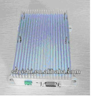
Devol Robot Simulator first screenshot
And here is the code that actually assembles the robot:

void LimbRigController::buildRig(){
    Vector center(-2,0,5);
    int NUM_LEGS=6;
    Vector axisBase(1,0,0);
    float thighToShinRatio=0.75;
    float legLength=1.0;
    float innerRad=0.5;
    float kneeRad=innerRad+(legLength*thighToShinRatio)/(legLength*thighToShinRatio+legLength/thighToShinRatio);
    float toeRad=kneeRad+(legLength/thighToShinRatio)/(legLength*thighToShinRatio+legLength/thighToShinRatio);
    float kneeHeight=0.0;
    float stepAng=(360)/NUM_LEGS;
    float ang=0;
    float legRadius=0.1;
    float baseRadius=2;
    DynamicObject *base=new DynamicObject(world,space,center,center +Vector(0,0.01,innerRad/baseRadius),Vector(0,0,1),baseRadius,0x008888ff,DynamicObject::CYL);
    //base->join(0,center,Vector(0,0,1));
    dobs.push_back(base);
    for(int i=0;i pelvis(0,innerRad,0);
        pelvis.rotate(ang,0,0,1);
        pelvis+=center;
        Vector knee(0,kneeRad,kneeHeight);
        knee.rotate(ang,0,0,1);
        knee+=center;
        Vector toe(0,toeRad,0);
        toe.rotate(ang,0,0,1);
        toe+=center;
        Vectoraxis=axisBase;
        axis.rotate(ang,0,0,1);
        DynamicObject *thig=new DynamicObject(world,space,pelvis,knee,axis,legRadius,0x00ff8888,DynamicObject::CYL);
        DynamicObject *shin=new DynamicObject(world,space,knee,toe,axis,legRadius,0x0088ff88,DynamicObject::CYL);
        base->join(thig,pelvis,axis,-M_PI*0.5,M_PI*0.5);
        shin->join(thig,knee,axis,-M_PI*0.5,0);
        dobs.push_back(thig);
        dobs.push_back(shin);
        ang+=stepAng;
    }
}

2013-08-09

Sourcing radio modem

I have combed alibaba again. That site is really full of interesting prospects!

This time I went looking for radio modems. The robot will have conventional WIFI and GPRS/3G/LTE access, but I thought that as a more general purpose, fail-safe and cheaper alternative (3G is expensive), It would be neat to have a FM radio on board. Just look at all the goodies!

Radio modem with 20km range from alibaba.com

I made sure to hide my VISA card someplace safe first.

ODE instead of IKFast

After working with IKFast for a while, I realized that the OpenRAVE + IKFast combo is overkill for my purpose, and It might not do what I need/want. I wrote my robot definition in XML based on one of the examples, loaded it in OpenRAVE and all was dany, except that it was really hard to work with. I have instead shifted my effort to creating a custom software in C++ / OpenGL / Qt5 / ODE.

Open Dynamics Engine joint types


The idea is to construct a model of the robot using ODE bodies connected with hinges, and then fit the model with linear motors in place of the linear actuators. The model will be constructed with realistic masses, sizes and motor speeds and torques in an environment with realistic ground friction and gravity. So this model will in many ways simulate a real hardware robot, with quirks and numerical errors in place.

Then the next step is to write a layered stack of controller logic that only receive as input the physical properties of the robot such as the limb sizes, masses and so on plus the robot state in the form of linear actuator position readings and the actual position of the limbs in the simulation.

By carefully crafting the logic in each layer of the stack, I can create a feedback loop that continuously "improves" the simulated state of the robot so that it resembles the desired configuration as much as possible.

Each layer will have its separate well defined set of responsibilities and well defined interfaces to the neighboring layers, allowing for experimentation within each confined layer bu exchanging modules.

This model will most likely make the work of finding good parameters for the robot much easier. Trusting the results will be easier.

2013-08-04

Anatomy of a robot limb

For simplicity I have decided to keep all 6 limbs of Devol identical. Each limb will be interchangeable with any other. This I hope will make building and maintaining the limbs much quicker and cheaper due to reuse, but the design process might take longer because now I have to ensure that the one design i decide upon actually will work for all 6 legs.

I have been thinking a lot, and created a 3d model for simulating the possible limb configurations. I have also managed to install OpenRave, and I have started learning to use it by adapting one of the example robot definition XML files while reading some of its tutorials on-line.

I have also looked at realistic actuators that might fit into the designs on global sourcing sites such as alibaba. For example I have received a quotation at 22USD per piece for 20pieces of this nice little actuator. Since I will need 18 of them, this is good news.

FY011C Linear actuator 12VDC at FOB 22USD/20pcs
The idea is that instead of having geared motors at the joins, I will have linear electro-mechanical actuators in a configuration that is typical for hydraulic and pneumatic systems. The benefits are many:
  • The design is simple
  • The resulting robot will be more solid due to the separation of hinges and force in joints.
  • Reaching higher precision in the actuators is easier than with geared motors due to the available flexibility of mounting positions.
  • The actuators will actually be cheaper due to their outspread use in furniture.
  • The actuators will remain static under load with 0 power drain.
  • The actuators are available with built in position sensors and end switches
  • The actuators are available with IP ratings for dust and water resistance. The one I found was rated IP66
  • The choice of available actuators is huge with all sorts of quality, precision, speed and load requirements.
 But how can I calculate the required dynamic and static forces? I found this great site that appears to be centered around building another hexapod. They have a head start, I better shape up!

Anyhow they made a series of tutorials, one which was very useful for my project, namely the PDF about simple hydraulics joints. I can warmly recommend it due to its simplicity and completeness.

My take-away was this figure with the matching formula:
Shamelessly stolen without permission from http://projecthexapod.com


Linear Piston Force * Moment Arm = Torque @ Joint 


Now I'll just have to find out the value for all my variables...


2013-08-01

3D rig

I have used  Light Wave since version 5.0, and it is a great 3D modeling and animation program with really long traditions. It has support for inverse kinematics, so it is perfect for experimenting with different models of the robot.  I have made a 3D model and animated it.

The purpose is to find optimum leg configurations, sizes and placements. I can also use the model to predict what kind of forces and precision I will need in my actuators. This was the greatest take-away from my first limb prototype, the fact that I need to have actuators with more torque and a design with much more sturdy joints. This is my first result. Its a single walk cylcle: